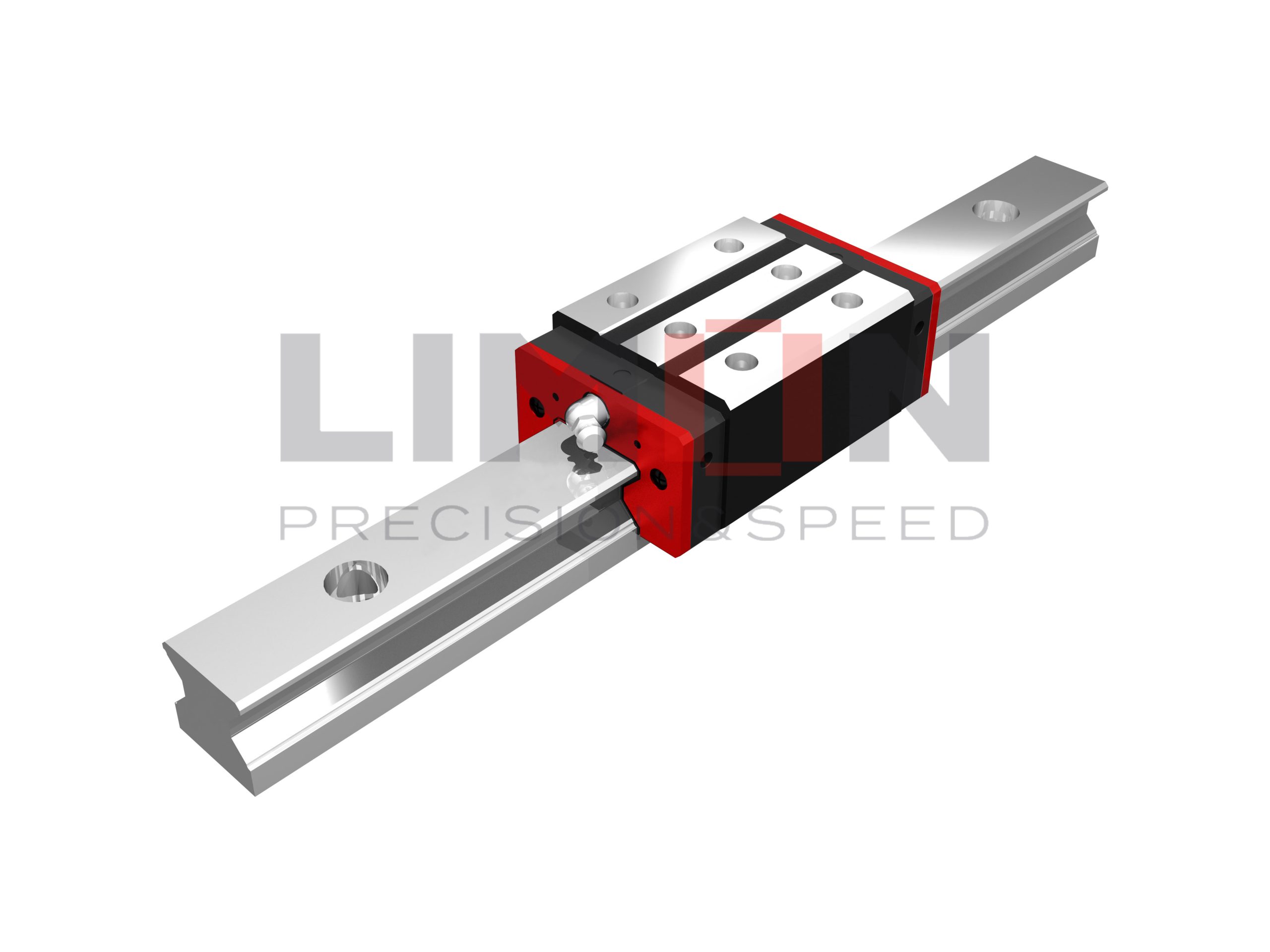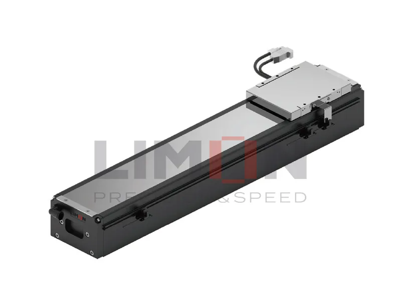

Model NO. | Dimensions of | Dimensions of | Dimensions of | Mounting Bolt for Rail | Basic Dynamic Load Rating | Basic Static Load Rating | Static Rated Moment | Weight | |||||||||||||||||||||||
MR | MP | MY | Block | Rail | |||||||||||||||||||||||||||
H | H1 | N | W | B | B1 | C | L1 | L | K1 | K2 | G | MxL | T | H2 | H3 | WR | HR | D | h | d | P | E | (mm) | C(kN) | C0(kN) | ||||||
RL15CA | 24 | 4 | 9.5 | 34 | 26 | 4 | 26 | 45 | 68 | 13.4 | 4.7 | 5.3 | M4x5.5 | 6 | 3.6 | 6.1 | 15 | 16.5 | 7.5 | 5.7 | 4.5 | 30 | 20 | M4x16 | 11.3 | 24 | 0.311 | 0.17 | 0.17 | 0.2 | 1.8 |
RL20CA | 30 | 5 | 12 | 44 | 32 | 6 | 36 | 57.5 | 86 | 15.8 | 6 | 5.3 | M5x6 | 8 | 4.3 | 4.3 | 20 | 21 | 9.5 | 8.5 | 6 | 30 | 20 | M5x20 | 21.3 | 46.7 | 0.647 | 0.46 | 0.46 | 0.40 | 2.76 |
RL20HA | 50 | 77.5 | 106 | 18.8 | 26.9 | 63 | 0.872 | 0.837 | 0.837 | 0.53 | |||||||||||||||||||||
RL25CA | 36 | 5.5 | 12.5 | 48 | 35 | 6.5 | 35 | 64.5 | 97.9 | 20.75 | 7.25 | 12 | M6x8 | 9.5 | 6.2 | 6.2 | 23 | 23.6 | 11 | 9 | 7 | 30 | 20 | M6x20 | 27.7 | 57.1 | 0.758 | 0.605 | 0.605 | 0.61 | 3.08 |
RL25HA | 50 | 81 | 114.4 | 21.5 | 33.9 | 73.4 | 0.975 | 0.991 | 0.991 | 0.75 | |||||||||||||||||||||
RL30CA | 42 | 6 | 16 | 60 | 40 | 10 | 40 | 71 | 109.8 | 23.5 | 8 | 12 | M8x10 | 9.5 | 6.5 | 6.5 | 28 | 28 | 14 | 12 | 9 | 40 | 20 | M8x25 | 39.1 | 82.1 | 1.445 | 1.06 | 1.06 | 0.90 | 4.41 |
RL30HA | 60 | 93 | 131.8 | 24.5 | 48.1 | 105 | 1.846 | 1.71 | 1.71 | 1.16 | |||||||||||||||||||||
RL35CA | 48 | 6.5 | 18 | 70 | 50 | 10 | 50 | 79 | 124 | 22.5 | 10 | 12 | M8x12 | 12 | 9 | 9 | 34 | 30.2 | 14 | 12 | 9 | 40 | 20 | M8x25 | 57.9 | 105.2 | 2.17 | 1.44 | 1.44 | 1.57 | 6.06 |
RL35HA | 72 | 106.5 | 151.5 | 25.25 | 73.1 | 142 | 2.93 | 2.60 | 2.60 | 2.06 | |||||||||||||||||||||
RL45CA | 60 | 8 | 20.5 | 86 | 60 | 13 | 60 | 106 | 153.2 | 31 | 10 | 12.9 | M10x17 | 16 | 10 | 10 | 45 | 38 | 20 | 17 | 14 | 52.5 | 22.5 | M12x35 | 92.6 | 178.8 | 4.52 | 3.05 | 3.05 | 3.18 | 9.97 |
RL45HA | 80 | 139.8 | 187 | 37.9 | 116 | 230.9 | 6.33 | 5.47 | 5.47 | 4.13 | |||||||||||||||||||||
RL55CA | 70 | 10 | 23.5 | 100 | 75 | 12.5 | 75 | 125.5 | 183.7 | 37.75 | 12.5 | 12.9 | M12x18 | 17.5 | 12 | 12 | 53 | 44 | 23 | 20 | 16 | 60 | 30 | M14x45 | 130.5 | 252 | 8.01 | 5.4 | 5.4 | 4.89 | 13.98 |
RL55HA | 95 | 173.8 | 232 | 51.9 | 167.8 | 348 | 11.15 | 10.25 | 10.25 | 6.68 | |||||||||||||||||||||
Note: 1. 1kgf = 9.81N | |||||||||||||||||||||||||||||||
2. The theoretical dynamic rated load is C100R,if necessary C50R conversion formula is as follwos : C50R = 1.23 x C100R | |||||||||||||||||||||||||||||||


